Monday, 11 February 2013

Stirling Engine Blog 16 January 30 2013

I did not do any physical work on the engine today as I was in Thermo King discussing both the project and the PhD application.

Thermo King were kind enough to order me the following (expected within a week):
  • Flowmeter for measuring the coolant loop flowrate
  • Power supply for the pressure transducer
  • Gas Hoses and fittings for connecting to the transducer
  • Wall box for mounting the sensors
  • Selection of terminal blocks for wiring
Shown below is a similar pressure transducer setup (which I hope to replicate):

Tuesday, 29 January 2013

Stirling Engine Blog 15 January 29 2013


I ran the engine today for 60 minutes using the new 800 W load. It appears to have worked exactly as planned - the unit's heater clamp did not come on even though the batteries were more or less fully charged at the start of the test. The coolant system reach equilibrium at around 42°C. The system reached steady state around 50 minutes into the test. 
Electric Heater used as battery load

Water condensing out of the exhaust gas (note a single droplet at the base of right angle fitting). The shape of the exhaust flue makes the fowl water drain ineffective and so the water leaks out of the seal. This is not an issue as it can be collected with a drip tray underneath. After about 30 minutes of runtime only about 20ml of water leaked.

Today's key data:
The system reaches a steady state at around 50 minutes into the test. The coolant system stays stabilises at around 42°C with the mains pressure at max flowrate. During efficiency tests, it will be necessary to let the coolant reach its setpoint temperature (60°C) to give a realistic efficiency measurement.

Monday, 28 January 2013

Stirling Engine Blog 14 January 28 2013

As mentioned in previous blog posts, the biggest unresolved problem was connecting the secondary heat exchanger to the mains water tap. It was necessary to join a standard garden hose to 3/4" qualpex - this is a very unusual combination and it is almost certainly not available as a standard fitting in a plumbing shop. I decided to quickly machine a small insert on my lathe that would allow me to join the flexible pipes. Whilst not very aesthetic the jubilee clip/rubber tubing has proven to be extremely effective and simple to use. 

Machining the part from a piece of scrap aluminium
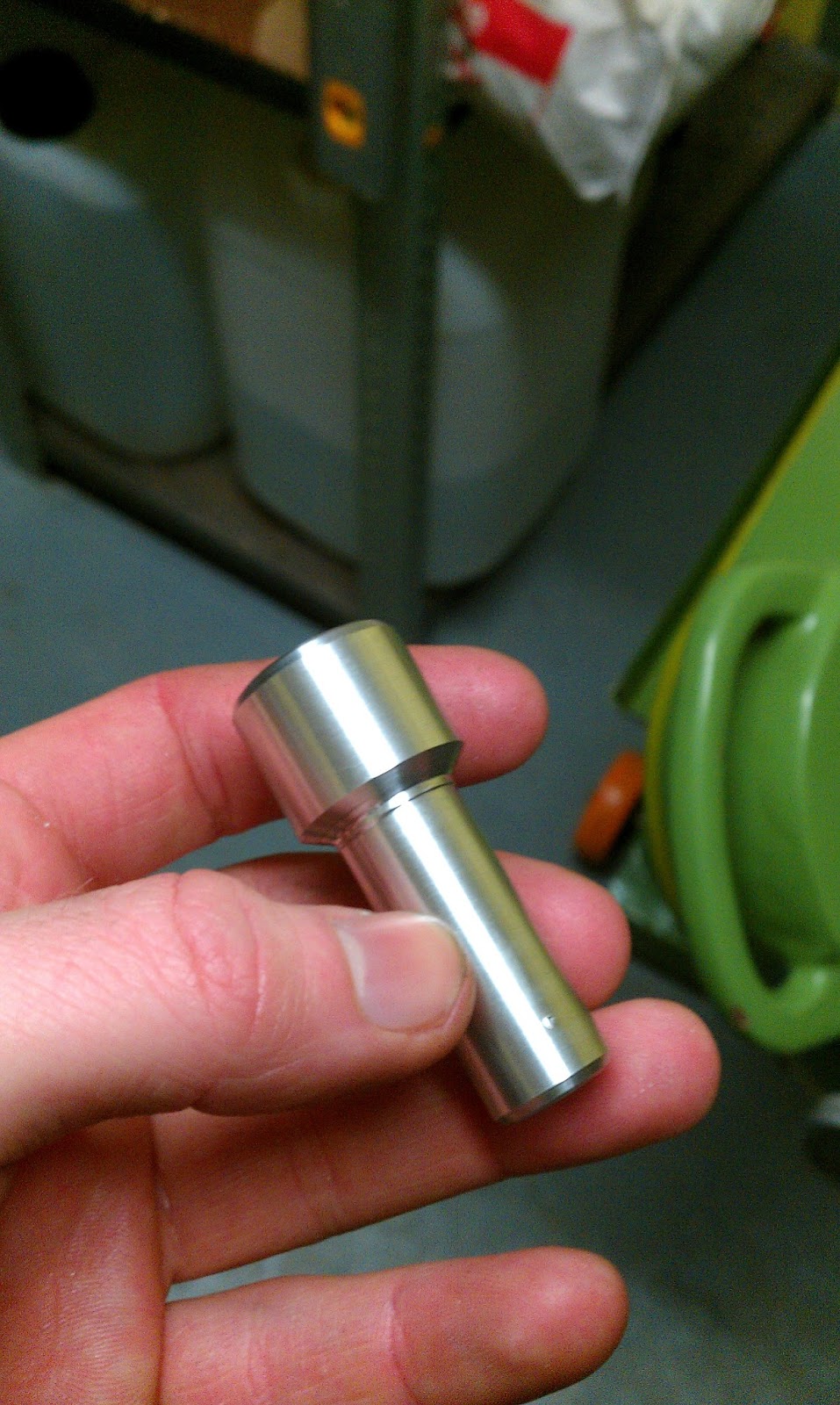
Finished part

Preparing to join the two hoses

The garden hose fits tightly around the insert

The larger diameter hose also fits well. This larger hose just connects onto the qualpex.

Jubilee clips added for additional safety. The interference fit is probably sufficient

I replaced the fitting on the tap with a standard garden hose quick release

With the last of the plumbing problems solved, I hooked up the inverter and a small 250W heater load. I intend on replacing this with an 800W heater in the coming days to act as the proper load for the engine to slow the rate of battery charging.

Batteries and inverter setup


View of the test area (note MicroMon running on the computer)

All of the major systems work on the engine is now completed. There are only minor jobs remaining, mostly related to adding various sensors to the setup which will be logged by LabView.

These include:


  • Pressure Transducer - To view the pressure levels inside the engine and keep an eye on any leakage
  • Water Flow Meter - T measure the flow rate of mains water pressure through secondary heat exchanger
  • Water Flow Meter - To measure the flow rate inside the cooling loop (possibly unnecessary)
  • Multiple Thermocouples - To measure heat rejected to cooling circuit and to mains water dump


I also tested the engine with the new secondary heat exchanger dump. It significantly slowed the heating rate of the cooling system. It appeared to stabilise at around 40°C even with around 10 amps going into the heater clamp (the batteries had switched to absorption charge). I ran the engine for a total of about 30 minutes and logged the run using MicroMon.

Today's data. Tblock (blue) is a proxy for the cooling system temperature as both were in rough equilibrium. The key thing to notice is that even with the clamp heater activated, the secondary heat exhanger is able to dump enough heat out of the system to maintain more or less constant coolant temperature. 

Saturday, 26 January 2013

Stirling Engine Blog 13 January 26 2013


I did not have time to do any physical work on the engine today. I did however manage to take a look at some of the data taken from Thursday's test run and graph it (shown below).

There are still a number of tasks that remain to be completed before the engine is fully operational:
  • Connect Inverter (the battery clips need to be replaced with rings)
  • Machine an adapter fitting for the tap (garden hose to 3/4" qualpex)
  • Install Labview of the cell computer
  • Get a suitably sized load for the inverter (~800 W)

Preliminary view of some key engine parameters (Exhaust Temperature, Engine Block Temperature, Power Output). Note that the data logging was only switched on part way through the engine test and does not have show the engine startup behaviour.

Stirling Engine Blog 12 January 24 2013


I made a good deal of progress today with the engine. I decided to bring in my own drill in order to do some trivial tasks that were taking too long for to be done by others. I mounted the header tank board to the diesel engine frame and I also mounted the coolant pump to the wall. The header tanks are now secure on top of the diesel engine frame and reasonably well isolated from the Stirling engine. 

Exhaust duct in place and header tanks filled and mounted on the secured board

I also spent a good deal of time connecting the new radiator fittings and reinstating the radiator and associated plumbing. As mentioned in the previous blog, I incorporated a drain valve into the system which greatly simplifies draining the whole system.

New valves on the radiator. Note the drain valve on the right hand line of the radiator

After troubleshooting all of the plumbing and bleeding both the coolant and fuel lines of air I proceeded to test fire the engine for a short 10 minute run. It is not possible to run for any longer than this as the heat dump quickly saturates. The engine ran smoothly with no errors. I logged a portion of this data which will be discussed in a later blog.


Stirling Engine Blog 11 January 23 2013


I put the exhaust duct up today, it was relatively straightforward as the flexible duct fits perfectly over the exhaust flue. I am still waiting on the aluminized tape to make a proper seal at the base near the engine.
During the first test charge of the plumbing system (with just water and no glycol), I had a major leak in one of the radiator fittings which forced me to drain the whole system. The radiator had 2 compression fittings connected to it (jury-rigged). The fittings were not the correct fittings for the radiator and were only a temporary measure during the initial tests at home. The thread on the connecting nut appears to be stripped or otherwise damaged. It was necessary to go back to Heat Merchants and pick up some new radiator valves. I've decided to put in the proper radiator valves and use 1/2" to 3/4" straight compression fittings to make them compatible with the qualpex. I've also decided to incorporate a drain valve in the system to make draining the system easier.

Radiator disconnected from circuit

Radiator fitting that needed to be replaced. The thread on the silver hex ring is damaged and it was necessary to replace the whole fitting (this also required getting a radiator spanner - a 1/2" allen key essentially)

Tuesday, 22 January 2013

Stirling Engine Blog 10 January 22 2013


Pat did an excellent job of making an exhaust pipe. He threaded some thick tubing using a lathe and then welded the joint making it into a single piece. He then gave the tube another pass on the lathe to clean it up so that the whole arrangement fits flush inside of the flexible ducting. I plan to fit the exhaust and duct tomorrow and will use some aluminized tape to seal the joint near the engine exhaust.

Welded gunbarrel fitting with fabricated tubing

Exhaust pipe in place

I connected the fuel line and pump also. I decided to replace the connections on the fuel pump as they were frayed and loose. I used some barrel crimps and positioned them so that polarity reversal wouldn't be possible.

Blue barrel crimps on the fuel pump connections

In addition to the exhaust, I rerouted some of the plumbing to tidy it up but there is still some more work to be done before the rig is in an acceptable condition. Pat also made a stand for the header tanks out of a sheet of plywood. The tanks sit flat on the sheet with their outlets coming out through holes in the sheeting.

Rerouted plumbing (some work still needed). Note white fuel line and coolant header tank (extreme right corner)

All that remains to be done:
  • Get the inverter installed and hooked up
  • Mount the coolant pump to the wall
  • Connect the cold water pipe to the tap
  • Charge and bleed the coolant system
  • Charge and bleed the fuel system